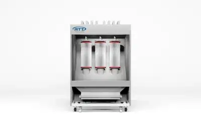
Cartridge Batch Powder Coating Booth
Self-Cleaning Filtration. Built for Batch Powder.
RTT Finishing Solutions’ Cartridge Batch Powder Coating Booths combine an open-face booth enclosure with an integrated cartridge collector module, purpose-built for small to mid-size powder coating operations. Integrated booth systems (RPB series) range from 8 to 12 feet wide with airflow from 5,000 to 11,000 CFM at 3 inches static pressure. Standalone cartridge collector modules (RPC series) are available from 4,000 to 8,000 CFM for pairing with existing enclosures.
The cartridge collector’s pulse-purge system is what separates this booth from a standard bag-filter design. As powder loads the cartridge filters and negative pressure rises, a timer-activated sequence of air purging valves pulses accumulated powder off the filters and into a removable drawer below — restoring airflow to design levels without stopping the line. A door-mounted Magnehelic gauge and pressure switches provide continuous filter monitoring, with automatic shutdown if final filter pressure exceeds its set point.
All filtered air recirculates back into the booth, eliminating external exhaust and make-up air requirements. The integrated control panel ships NEMA 12, UL-listed, factory-mounted, wired, and tested. An onboard VFD controls fan speed to match production load. Every cartridge batch powder booth meets OSHA and NFPA regulations.
Features
- Open-face, open-front booth design with integrated rear cartridge collector module
- 18-gauge prime-quality galvanized steel construction; laser-cut, precision-formed panels; nut-and-bolt assembly
- Cartridge collector module: factory-assembled, powder-coated white mild steel; primary cartridge filter module and final filter module; removable powder drawer
- Pulse-purge self-cleaning system: timer-activated air purging valves clear cartridge filters of accumulated powder during operation
- Collector module recirculates filtered air back into the booth (no external exhaust required)
- NEMA 12, UL- and ETL-listed control panel: factory-mounted to collector module, pre-wired and tested
- Automatic or manual cartridge filter pulse-down mode
- Door-mounted Magnehelic gauge for real-time cartridge filter pressure monitoring
- Pressure switches monitor final filter pressure; trigger warning and/or automatic shutdown at set point
- Variable Frequency Drive (VFD) controls fan speed
- Air solenoid valve interlocked to exhaust fan and spray application air supply
- E-Light LED fixtures: 22-gauge steel housing, powder-coated white; 4,000 and 8,000 lumen models
- E-Light ETL-listed for US and Canada: Class 1 Division 2 Groups A, B, C, D; Class 2 Division 2 Groups F and G; no safety interlock required
- Lighting levels engineered using photometric software
- Meets and exceeds all applicable OSHA and NFPA regulations
Benefits
- Maintain consistent airflow throughout production runs — the pulse-purge system clears cartridge filters automatically on a timer, without stopping the line or manual filter service.
- Recirculate filtered air back into your facility — the collector module returns clean air to the booth, eliminating external exhaust requirements and make-up air costs.
- Reduce operating energy costs — the integrated VFD adjusts fan speed to match actual load, lowering amp draw during lighter production cycles.
- Monitor filter health in real time — the door-mounted Magnehelic gauge and pressure switch system alert operators before filter loading degrades finish quality or triggers a shutdown.
- Simplify installation — the control panel ships factory-mounted, wired, and tested on the collector module, reducing field wiring time and startup risk.
- Recover overspray powder for reuse — the optional fluidized bed enables powder reclamation directly from the collector’s removable powder drawer.
- Maintain code compliance out of the box — every booth meets OSHA and NFPA regulations, with ETL-listed controls included standard.
Technical Specifications
RTT can design and build spray booths in a variety of sizes and configurations. Although our team can engineer a custom booth to fit your needs, below are standard sizes that are quickly available to you.
Cartridge Collectors
| Model Number | Interior Dimensions | Exterior Dimensions | Airflow | Modules | Cartridge Filters | Final Filters | Fan HP | Lights | S&G | ||||
|---|---|---|---|---|---|---|---|---|---|---|---|---|---|
| Width | Height | Length | Width | Height | Length | CFM | Qty | Qty | Qty | HP | Qty | S&G | |
| RPC-4000-S | N/A | N/A | N/A | 4'8" (w/CP 5'10") | 8'8" (w/MFD 9'4") | 4'4" (w/Motor 6'1") | 4,000 @3" SP | 1 | 5 | 4 | 5HP | 1 | N/A |
| RPC-5000-S | N/A | N/A | N/A | 4'8" (w/CP 5'10") | 8'8" (w/MFD 9'4") | 4'4" (w/Motor 6'1") | 5,000 @3" SP | 1 | 5 | 4 | 7.5HP | 1 | N/A |
| RPC-6000-S | N/A | N/A | N/A | 6' (w/CP 7'2") | 8'8" (w/MFD 9'4") | 5'3" (w/Motor 6'2") | 6,000 @3" SP | 1 | 7 | 6 | 7.5HP | 1 | N/A |
| RPC-7000-S | N/A | N/A | N/A | 6' (w/CP 7'2") | 8'8" (w/MFD 9'4") | 5'3" (w/Motor 6'2") | 7,000 @3" SP | 1 | 7 | 6 | 10HP | 1 | N/A |
| RPC-8000-S | N/A | N/A | N/A | 6' (w/CP 7'2") | 8'8" (w/MFD 9'4") | 5'3" (w/Motor 6'2") | 8,000 @3" SP | 1 | 7 | 6 | 10HP | 1 | N/A |
Powder Booths
| Model Number | Interior Dimensions | Exterior Dimensions | Airflow | Modules | Cartridge Filters | Final Filters | Fan HP | Lights | S&G | ||||
|---|---|---|---|---|---|---|---|---|---|---|---|---|---|
| Width | Height | Length | Width | Height | Length | CFM | Qty | Qty | Qty | HP | Qty | S&G | |
| RPB-08-07-7.5-00-S | 8' | 7' | 7'6" | 8'4" | 9'4" | 13'8" | 5,000 @3" SP | 1 | 5 | 4 | 7.5HP | 1 | 1 |
| RPB-08-08-7.5-00-S | 8' | 8' | 7'6" | 8'4" | 9'4" | 13'8" | 6,000 @3" SP | 1 | 7 | 6 | 7.5HP | 1 | 1 |
| RPB-08-10-7.5-00-S | 8' | 10' | 7'6" | 8'4" | 10'2" | 13'8" | 7,000 @3" SP | 1 | 7 | 6 | 10HP | 1 | 1 |
| RPB-10-07-7.5-00-S | 10' | 7' | 7'6" | 10'4" | 9'4" | 13'8" | 6,000 @3" SP | 1 | 7 | 6 | 7.5HP | 1 | 1 |
| RPB-10-08-7.5-00-S | 10' | 8' | 7'6" | 10'4" | 9'-4" | 13'8" | 7,000 @3" SP | 1 | 7 | 6 | 10HP | 1 | 1 |
| RPB-10-10-7.5-00-S | 10' | 10' | 7'6" | 10'4" | 10'2" | 13'10" | 9,000 @3" SP | 1 | 9 | 9 | 10HP | 1 | 2 |
| RPB-12-07-7.5-00-S | 12' | 7' | 7'6" | 12'4" | 9'4" | 13'8" | 8,000 @3" SP | 1 | 7 | 6 | 10HP | 1 | 2 |
| RPB-12-08-7.5-00-S | 12' | 8' | 7'6" | 12'-4" | 9'10" | 13'10" | 9,000 @3" SP | 1 | 9 | 9 | 10HP | 1 | 2 |
| RPB-12-10-7.5-00-S | 12' | 10' | 7'6" | 12'4" | 10'2" | 13'10" | 11,000 @3" SP | 1 | 9 | 9 | 10HP | 1 | 2 |
Options & Configurations
- Standalone cartridge collector modules (RPC series, 4,000–8,000 CFM) for pairing with existing booth enclosures
- Integrated cartridge booth systems (RPB series, 5,000–11,000 CFM) with booth enclosure and collector as a single unit
- Powder-coated white exterior finish (upgrade from standard galvanized)
- Optional fluidized bed for powder reclamation from the collector drawer
- Conveyor and crane slots/openings for overhead material handling integration
- Custom sizes and configurations available by engineering request — contact RTT customer service for pricing and lead time
Bright, Efficient Lighting – Included
Each booth includes E-Light LED lighting, offering:
- Lower energy consumption
- True color rendering
- Extended life and reduced maintenance costs
LED housings are constructed of 22-gauge steel and powder-coated white. E-Lights are ETL listed for U.S. and Canada, rated Class 1 Division 2 (Groups A–D) and Class 2 Division 2 (Groups F & G).
RTT lighting is calculated and engineered using photometric software. E-Light fixtures are ETL listed and designed for proper use in spray booths. Because of this, our E-Light does not require a safety interlock saving on installation cost and additional maintenance.
Control Panels
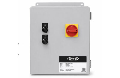
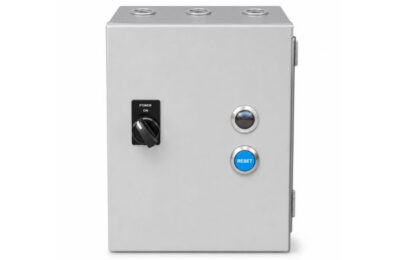
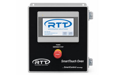
RTT offers pre-wired motor starters, UL-listed control panels, VFD controls, and optional touchscreens to simplify operation, fan speed adjustment, and booth balancing. All panels feature a single-point connection for quick and easy installation.
UL Listed Standard
- Control Panels
Magnetic Motor Starter
- Control Panels
SmartTouch Touchscreen
- Control Panels
Variable Frequency Drive
- Control Panels

Services
RTT provides end-to-end services tailored to every phase of your project, so you never have to look further than one trusted partner.
Custom Engineered Solutions
Maintenance
Product Training
Installations
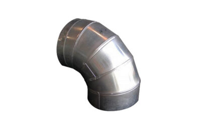
Ductwork
Help and Support
Access the resources, documentation, and technical support information you need to keep your RTT equipment operating safely, efficiently, and at peak performance.
Product Literature
Frequently Asked Questions
How Do I Adjust the Pulse-Down Timing for My Powder Booth Cartridge Collector?
1. Turn off the power to the control panel and open the door. Wait 2 minutes for the VFD display to turn off.
2. Turn on the power to the control panel and start the fan.
3. Locate the Dwyer timer board and press the “Select” button, “Last Output” LED will illuminate, and the display will show a value.
4. Press the “Select” button, “Time Off” LED will illuminate, and the display will show a value. Use the Up/Down buttons to change the value to the desired amount of time between pulses (in seconds). Quicker pulsing will allow filters to clean faster but will require more compressed air.
5. Press the “Select” button, “Time On” LED will illuminate and the display will show a value. Use the Up/Down buttons to change the value to the desired amount of time each pulse valve will stay on (default is 100 milliseconds).
6. Press the “Select” button several times until the “Process” LED illuminates. The programming is now complete. Stop the fan, turn off the power to the control panel. Close the door and wait 2 minutes for the VFD to de-energize, then turn the power back on.
How Do I Adjust Airflow on My Powder Collector?
The control panel is equipped with a “Fan Speed” knob on the door. Adjust the knob to a higher value for more airflow, or a lower value for less airflow.
Where Should the Temperature Sensor Be Located on My Spray Booth?
RTT recommends that the temperature probe be in the discharge ductwork of the Air Make-up Unit (AMU). The probe is to be located as far from the discharge location of the AMU as possible before entering the paint booth intake plenum. This configuration helps to avoid sharp spikes in temperature and will even out the ramp and soak time of the burner. Eliminating the possibility of an over-temperature situation inside the AMU. In rare instances, the temperature probe may be in the intake plenum of the spray booth. Please consult with RTT Technical Support before locating the temperature probe anywhere other than the AMU discharge ductwork.
Why Are My Spray Booth Doors Being Blown Open?
This is typically caused by excessive incoming gas pressure affecting system balance. When gas pressure exceeds regulator ratings:
• Airflow and burner output become unstable
• The system may create positive pressure inside the booth
• Doors can blow open due to improper pressure differential
Check the valve train regulator, system gas pressure, and follow the manufacturer’s recommended pressure ranges.
My Spray Booth and Oven Controls Require a Password to Change Settings - What Is It?
Operator passcode is 2050
Oven – All passcodes in the Oven Operation & Maintenance manual. Maintenance passcode is 1111
My Exhaust Fan Is Not Running Even Though My Booth Has Power — What Could Be Causing It?
There could be several issues that could cause your exhaust fan not to operate. If you have confirmed you have power, do you have a fault on your Variable Frequency Drive (VFD)? Check to see if there is a fault code displayed on the VFD. Depending on the make and model of your VFD these codes can differ.
Additional Resources
Support Center

Frequently Asked Questions

Instructional Videos

Product Training
Related Products
Batch
- Powder Coating Booths
Pass Through
- Powder Coating Booths
Lab
- Powder Coating Booths