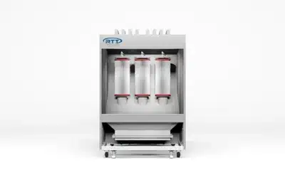
CT Series Air Makeup Unit
Fresh, Tempered Air. Built for the Finishing Industry.
The RTT Finishing Solutions CT Series Air Makeup Unit replaces 100% of the air exhausted from a spray booth enclosure or building with fresh, filtered, tempered outside air. Designed specifically for the finishing industry, the CT Series AMU ships with a custom control panel that includes an all-digital microprocessor PID controller with dual set point temperature control, a digital Magnehelic gauge, and user-adjustable recipes for spray, flash, cure 1, cure 2, and cool time — giving operators direct control over every stage of the finishing cycle.
The CT Series is built for cost-sensitive projects that still require professional-grade performance. A low-sound forward-curve fan, G90 galvanized construction, and automatic booth pressure control — delivered via an integrated VFD that manages the booth exhaust fan — make it a field-ready replacement for undersized or aging makeup air equipment. Automatic intake shutoff dampers, power profile dampers for burner optimization, and motorized auto gas control handle combustion and airflow management without manual adjustment. Standard 2-inch cleanable intake filters protect the heat exchanger and downstream components.
The CT AMU is ETL listed to ANSI Z83.25 – CSA3.19, covering both U.S. and Canadian installations. All combustion components meet applicable safety standards. Optional features include manual balance adjustments, prep mode, and recirculation for operations that need additional process flexibility.
Features
- Replaces 100% of exhausted booth or building air with fresh, filtered, tempered outside air
- ETL listed to ANSI Z83.25 – CSA3.19 (US and Canada)
- G90 galvanized steel construction
- Low-sound level forward-curve supply fan
- Automatic booth pressure control via integrated VFD on booth exhaust fan
- All-digital microprocessor PID controller with dual set point temperature control
- User-adjustable recipes for spray, flash, cure 1, cure 2, and cool time
- Digital Magnehelic gauge
- Control module with alarm history and technical information display
- Motorized auto gas control
- Intake shutoff damper with automatic actuator
- Power profile dampers for burner optimization
- Approved combustion components
- 2″ cleanable intake filters
Benefits
- Maintain booth pressure balance without manual fan adjustment — the integrated VFD controls the exhaust fan speed automatically for user-friendly pressure balancing.
- Protect finish quality year-round — tempered, filtered outside air replaces exhausted booth air continuously, preventing negative pressure, cold drafts, and contamination from entering the spray zone.
- Dial in every phase of the finishing process — user-adjustable recipes for spray, flash, cure 1, cure 2, and cool time give operators repeatable process control from the control panel.
- Reduce unplanned downtime — the control module stores alarm history and technical information for faster fault diagnosis.
- Lower installation and operating costs compared to higher-tier AMU series — lightweight construction and competitive pricing make the CT Series a practical choice for budget-conscious projects.
- Operate at lower sound levels — the forward-curve fan design reduces ambient noise compared to standard axial fan configurations.
- Deploy in the US or Canada without additional certification — ETL listed to ANSI Z83.25 – CSA3.19 covers both markets.
CT Series Air Makeup Unit - Selection Guide
Available for both indoor and outdoor applications, the CT air makeup units can be set up for vertical or horizontal configurations. Multiple discharge locations are available to help in the arrangement of custom layouts and critical dimensions.
| Specification | CT-118 | CT-120 | CT-122 | CT-125 | CT-127 | CT-130 | CT-133 |
|---|---|---|---|---|---|---|---|
| Airflow | |||||||
| CFM Range (SCFM) | 8,000–10,000 | 11,000–14,000 | 15,000–18,000 | 19,000–21,000 | 22,000–27,000 | 28,000–30,000 | 31,000–40,000 |
| External Static Pressure | 1/2" | 1/2" | 1/2" | 1/2" | 1/2" | 1/2" | 1/2" |
| Fan Motor | |||||||
| Horsepower (HP) | 5–7.5 | 7.5–15 | 15 | 20 | 15–20 | 20 | 20–30 |
| Amps @ 208V 3-Phase | 17.5–25.3 | 25.3–48.3 | 48 | 62 | 48.3–62.1 | 62 | 62.1–92 |
| Amps @ 230V 3-Phase | 15.2–22 | 22–42 | 42 | 54 | 42–54 | 54 | 54–80 |
| Amps @ 460V 3-Phase | 7.6–11 | 21–21 | 21 | 27 | 21–27 | 27 | 27–40 |
| Amps @ 575V 3-Phase | 6.1–9 | 9–17 | 17 | 22 | 17–22 | 22 | 27–32 |
| Burner & Fuel | |||||||
| Burner BTU Rating (Max) | 880,000–1,100,000 | 1,210,000–1,540,000 | 1,650,000–1,980,000 | 2,090,000–2,310,000 | 2,420,000–2,970,000 | 3,080,000–3,300,000 | 3,410,000–4,400,000 |
| Fuel Pressure (PSI) | 2 | 2 | 2 | 2 | 2 | 2 | 2 |
| Valve Train Inlet Size | 3/4"–1" | 1" | 1" | 1"–1 1/4" | 1 1/4" | 1 1/4" | 1 1/2" |
| Natural Gas Consumption (CFH) | 880–1,100 | 1,210–1,540 | 1,650–1,980 | 2,090–2,310 | 2,420–2,970 | 3,080–3,300 | 3,410–4,400 |
| Propane Consumption (CFH) | 555–693 | 762–970 | 1,040–1,248 | 1,317–1,456 | 1,525–1,871 | 1,941–2,079 | 2,149–2,773 |
Options & Configurations
- Manual balance adjustments
- Prep mode
- Recirculation
Custom configurations and sizing available – contact us for details.
Control Panels
RTT offers pre-wired motor starters, UL-listed control panels, VFD controls, and optional touchscreens to simplify operation, fan speed adjustment, and booth balancing. All panels feature a single-point connection for quick and easy installation.
UL Listed Standard
- Control Panels
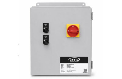
Magnetic Motor Starter
- Control Panels
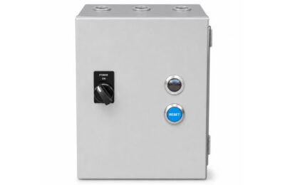
SmartTouch Touchscreen
- Control Panels
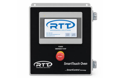
Variable Frequency Drive
- Control Panels

Services
RTT provides end-to-end services tailored to every phase of your project, so you never have to look further than one trusted partner.
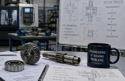
Custom Engineered Solutions
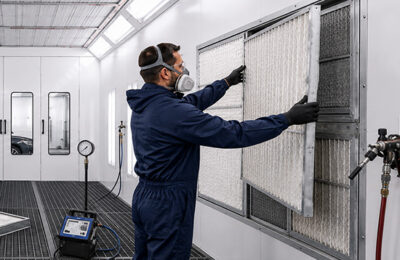
Maintenance
Product Training

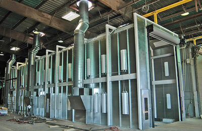
Installations
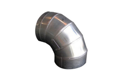
Ductwork
Help and Support
Access the resources, documentation, and technical support information you need to keep your RTT equipment operating safely, efficiently, and at peak performance.
Product Literature
Frequently Asked Questions
What Is the Passcode for My Air Makeup Unit (AMU)?
The standard operator passcode for the Air Makeup Unit (AMU) is:
• Operator: 2050
Where Should the Discharge Temperature Sensor Be Located?
RTT recommends placing the temperature probe in the AMU discharge ductwork, as far from the discharge point as possible before the air enters the paint booth intake plenum.
This placement:
• Prevents temperature spikes
• Ensures accurate temperature control
• Minimizes risk of over-temperature conditions inside the AMU
In rare situations, the sensor may be placed in the booth intake plenum. Contact RTT Technical Support before doing so.
Is Incoming Gas Pressure to the Valve Train and Burner Important?
Yes, proper gas pressure is critical for safe and reliable operation.
• Gas pressure must never exceed the maximum rating of the valve train regulator.
• Excess pressure can damage internal components or prevent the valve train from shutting off gas during a shutdown, creating a serious safety hazard.
• Too little pressure reduces burner BTU output and may cause low-gas safety faults.
Typical pressure ranges:
• AMUs: 1.5–2.5 PSI (varies by design; refer to drawings/manuals)
• Ovens: 2–5 PSI
Additional Resources
Support Center

Frequently Asked Questions

Instructional Videos

Product Training
Related Products
Batch
- Powder Coating Booths
Cartridge Batch
- Powder Coating Booths
Pass Through
- Powder Coating Booths
Lab
- Powder Coating Booths