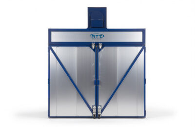
Batch Cure Chamber
Accelerated Cure Times. Built for Batch Production.
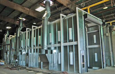
RTT Finishing Solutions’ Batch Cure Chambers accelerate the drying and curing of coatings on wood, metal, and non-metallic substrates after the application stage. Parts accumulate inside the chamber where filtered, heated air — supplied by an RTT Air Makeup Unit at temperatures up to 160°F — circulates through the enclosure to reduce cure time and improve part handleability for downstream processing. The system recirculates 80% of the chamber air through the exhaust plenum back into the space, with the remaining 20% exhausted to atmosphere, maximizing thermal efficiency across the cure cycle.
RTT Air Makeup Units deliver filtered air evenly throughout the chamber and are engineered for optimal fuel efficiency. A chamber-mounted temperature probe measures internal air temperature and adjusts the AMU output continuously, minimizing thermal variation across the load. Intake and exhaust filtration removes particulates that could affect finish quality during the cure cycle. The recirculation design maintains consistent temperature distribution without relying entirely on fresh heated air for every cycle.
Construction uses 18-gauge prime-quality galvanized steel panels and structural components, laser-cut and precision-bent for nut-and-bolt field assembly. Insulated panels are 20-gauge aluminized steel with 4-inch insulation as standard. Windowed personnel access doors are pre-hung in a heavy-gauge galvanized steel frame; the entry door is 36 inches wide. A slotted channel design reduces heat transfer at structural connections. Every RTT Batch Cure Chamber ships with E-Light LED lighting and a NEMA 12, ETL- and UL 508a-listed control panel with VFD for exhaust fan speed control.
Features
- 80% air recirculation through exhaust plenum back into chamber; 20% exhausted to atmosphere
- RTT Air Makeup Unit supplies filtered, heated air up to 160°F through intake plenum
- Chamber-mounted temperature probe measures and adjusts internal temperature continuously
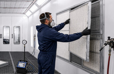
- Intake and exhaust filtration removes particulates from recirculated air
- 18-gauge prime-quality galvanized steel construction; laser-cut, precision-bent panels and structural components; nut-and-bolt assembly
- 20-gauge aluminized steel insulated panels with 4-inch insulation (standard)
- Slotted channel design reduces heat transfer at structural connections
- Windowed personnel access door: 36″ wide, pre-hung in heavy-gauge galvanized steel frame
- NEMA 12, ETL- and UL 508a-listed control panel with Variable Frequency Drive (VFD) for exhaust fan speed control
- E-Light LED lighting standard
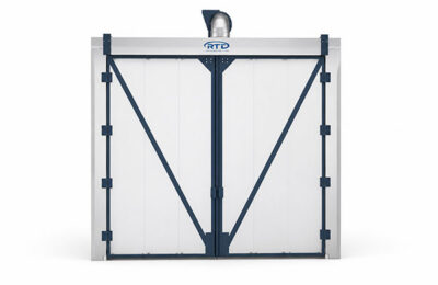
- Available in standard hinged-door/solid-back or pass-through configuration
- Complies with applicable NFPA regulations
Benefits
- Move parts through your finishing line faster — heated, filtered air at up to 160°F reduces cure time and improves part handleability for downstream processing.
- Reduce heating energy costs — the 80/20 recirculation design returns 80% of chamber air back into the cure space rather than exhausting and reheating it every cycle.
- Maintain consistent cure temperatures across the full load — the chamber-mounted probe adjusts AMU output continuously to minimize thermal variation.
- Protect finish quality during cure — intake and exhaust filtration removes particulates from recirculated air before they can settle on coated surfaces.
- Simplify installation — laser-cut, precision-bent panels and structural components align without custom fitting and bolt together in the field.
- Reduce lighting energy and maintenance costs — E-Light LED fixtures are standard on every batch cure chamber and carry a 5-year warranty.
- Control exhaust fan speed from a single panel — the NEMA 12, ETL- and UL 508a-listed control panel includes a VFD for user-friendly booth pressure balancing.
Technical Specifications
RTT provides three standard sized batch cure chambers that accommodate a wide range of curing needs. RTT can also offer custom sizes and configurations that can be engineered to meet site-specific needs.
| Model Number | Interior Dimensions | Nominal Door Opening | Exhaust Fan | Access Doors | 80% Recirc CFM |
Qty. Lights |
||||||
|---|---|---|---|---|---|---|---|---|---|---|---|---|
| Width | Height | Depth | Width | Height | Airflow | Size | HP | Qty | Type | |||
| BCC-12-08-16-P-SB | 12′ | 8′ | 16′ | 8′ | 8′ | 1,632 CFM | 18″ | 3/4 HP | 1 | Solid | 6,528 | 2 |
| BCC-14-10-22-P-SB | 14′ | 10′ | 22′ | 10′ | 10′ | 2,380 CFM | 18″ | 3/4 HP | 1 | Solid | 9,520 | 2 |
| BCC-16-16-34-P-SB | 16′ | 16′ | 34′ | 12′ | 16′ | 4,352 CFM | 18″ | 1.5 HP | 1 | Solid | 17,408 | 4 |
Alternative Configuration: Drive Through
Options & Configurations
- Custom height, width, and depth — all dimensions can be engineered to specific requirements
- Powder-coated white exterior finish (upgrade from standard galvanized)
- 2-inch insulated panels rated up to 180°F (upgrade from standard 4-inch panels)
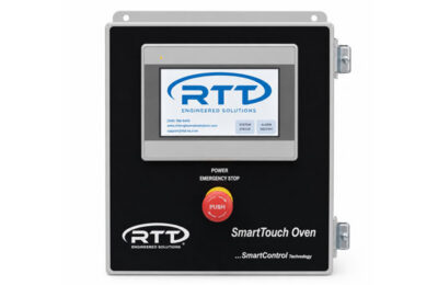
- SmartTouch PLC-based touchscreen control panel
- Roll-up, tri-fold, or bi-fold doors
- Drive-through (pass-through) configuration
Lighting
Every RTT Batch Cure Chamber ships with E-Light LED Light fixtures. Fixtures are constructed from 22-gauge powder-coated white steel and are available in 4,000 and 8,000 lumen models. E-Lights are ETL-listed for the US and Canada, rated Class 1 Division 2 (Groups A, B, C, D) and Class 2 Division 2 (Groups F and G). No safety interlock is required, reducing installation cost and ongoing maintenance. Lighting levels are calculated and engineered using photometric software.
Control Panels
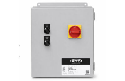
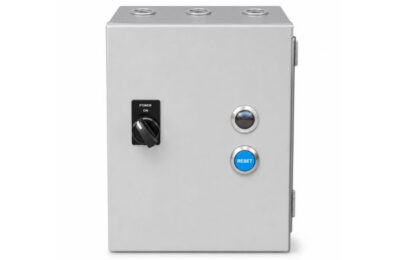
RTT offers pre-wired motor starters, UL-listed control panels, VFD controls, and optional touchscreens to simplify operation, fan speed adjustment, and booth balancing. All panels feature a single-point connection for quick and easy installation.
UL Listed Standard
- Control Panels
Magnetic Motor Starter
- Control Panels
SmartTouch Touchscreen
- Control Panels
Variable Frequency Drive
- Control Panels

Services
RTT provides end-to-end services tailored to every phase of your project, so you never have to look further than one trusted partner.
Custom Engineered Solutions
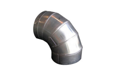
Ductwork
Installations
Maintenance
Product Training
Help and Support
Access the resources, documentation, and technical support information you need to keep your RTT equipment operating safely, efficiently, and at peak performance.
Product Literature
Frequently Asked Questions
What Does the LOC Code Mean?
LOC codes indicate specific safety or operational conditions detected by the control system:
• LOC 2: No establishment of flame within the safety time
• LOC 3: Air pressure fault
• LOC 4: Extraneous light detected
• LOC 5: Air pressure welded in working position
• LOC 6: Actuator fault
• LOC 7: Loss of flame
These alerts help protect the system and ensure proper burner performance.
Why Does the Burner Shut Off and Return to Purge Mode?
This typically indicates a failed air switch.
Your system uses air switches on the combustion fan, recirculation fan, and exhaust fan.
If one of these switches does not provide airflow, the system returns to purge for safety.
Why Does My Oven Overshoot the Set Temperature?
This typically indicates a failed air switch.
Your system uses air switches on the combustion fan, recirculation fan, and exhaust fan.
If one of these switches does not provide airflow, the system returns to purge for safety.
What Is the Required Gas Pressure?
Your oven should operate with gas pressure between 2 PSI and 5 PSI.
Pressures outside this range may affect burner performance or safety.
How Do I Download Temperature History?
You can download temperature history directly from the Smart Control panel:
1. Open the Maintenance tab
2. Select Temperature History
3. Click Export
4. Follow the on-screen instructions to save the file
What Is the Proper Incoming Gas Pressure for the Valve Train and Burner?
Proper gas pressure is critical for safe and reliable operation.
• Gas pressure must never exceed the maximum rating of the valve train regulator.
• Excess pressure can damage internal components or prevent the valve train from shutting off gas during a shutdown, creating a serious safety hazard.
• Too little pressure reduces burner BTU output and may cause low-gas safety faults.
Typical pressure ranges:
• Ovens: 2–5 PSI
Additional Resources
Support Center

Frequently Asked Questions

Instructional Videos

Product Training
Related Products
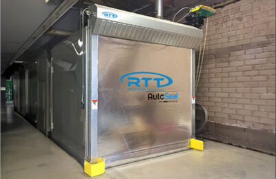
AutoSeal Oven Roll Up Door
- Accessories
Batch
- Ovens
CT Series
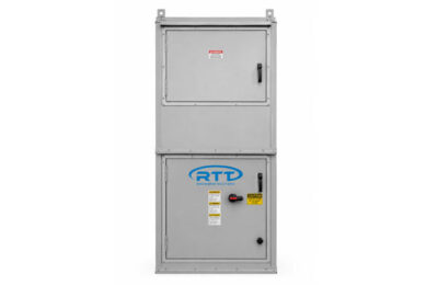
- Air Makeup Units
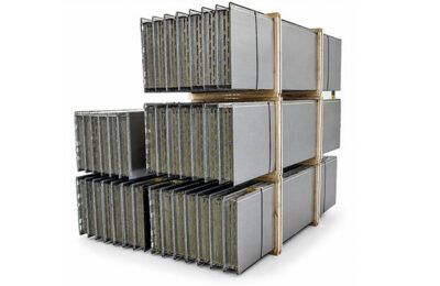
Insulated Oven Panel
- Accessories
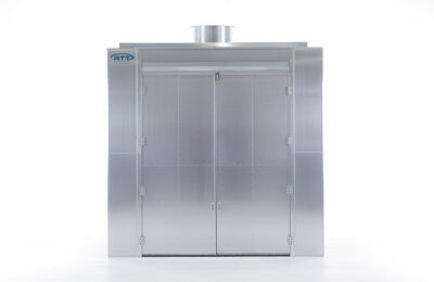
Process
- Ovens
SmartBatch Cure
- Controls
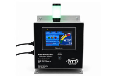
SmartTouch Touchscreen
- Control Panels
VHD Batch
- Ovens