Industrial Exhaust Chamber
Filtered Exhaust. Non-Sparking Construction. Built for the Finish Line.
RTT Finishing Solutions’ Industrial Exhaust Chambers remove harmful vapors and airborne particulate from paint spray and sanding operations across a wide range of industrial production environments. The chamber draws contaminated air through dry arrestor filters that trap overspray particles before the filtered air discharges through the exhaust stack to atmosphere. Standard configurations range from 4 to 20 feet wide and 7 to 12 feet tall, with airflow from 3,500 to 30,000 SCFM at ½-inch static pressure — covering the full range from small batch operations to high-volume production lines.
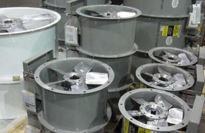
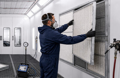
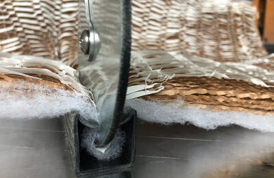
Every RTT exhaust chamber ships with high-efficiency W-Series RP Paint Arrestor blanket filters, secured by FilterLoc Paint Booth Seal technology for a tighter seal to the chamber frame, eliminating overspray bypass and simplifying filter changeouts. A tubeaxial exhaust fan – specifically designed for paint spray exhaust applications – powers airflow through the stack. All standard fans are non-sparking construction, with motor drive and bearings sealed from the exhaust air stream. An optional air solenoid valve interlocks the exhaust fan with the spray equipment air supply.
Construction uses 18-gauge prime-quality galvanized steel with structural steel reinforcement where required for strength and rigidity. RTT is the only paint booth manufacturer to offer a 5-year warranty. Control panels are available separately; an optional explosion-proof motor upgrade is required for use in flammable painting environments. Fire control systems are supplied by others.
Features
- Dry arrestor filtration: W-Series RP Paint Arrestor blanket filters trap airborne overspray; filtered air discharges through exhaust stack to atmosphere
- 18-gauge prime-quality galvanized steel construction; structural steel reinforcement added as required for strength and rigidity
- High-efficiency W-Series RP Paint Arrestor blanket filters included standard
- FilterLoc Paint Booth Seal filter retention technology seals filters to chamber frame; eliminates overspray bypass
- Tubeaxial exhaust fan designed specifically for paint spray exhaust chamber applications
- Non-sparking fan construction standard
- Motor drive and bearings sealed from the exhaust air stream
- Suitable for paint spray and sanding applications
- 5-year warranty
- Meets and exceeds all applicable OSHA and NFPA regulations
- Fire control systems supplied by others
Benefits
- Remove harmful vapors and overspray particulate from the production environment – dry arrestor filtration captures airborne particles before filtered air discharges to atmosphere.
- Accommodate paint spray and sanding applications from the same chamber design – the wide range of standard configurations covers most production requirements without custom engineering.
- Eliminate overspray bypass at the exhaust filter – FilterLoc technology seals W-Series RP Arrestor filters directly to the chamber frame, preventing unfiltered air from escaping around the filter media.
- Protect fan and motor components from the exhaust air stream – sealed motor drive and bearings extend service intervals and reduce unplanned downtime.
- Scale airflow precisely to your production line – 36 standard configurations from 3,500 to 30,000 SCFM let you match chamber capacity to actual exhaust requirements.
- Enjoy peace of mind with the industry’s only 5-year paint booth warranty
Sizes & Specifications
RTT can design and build exhaust chambers in a variety of sizes and configurations. Although our team can engineer a custom chamber to fit your needs, below are standard sizes that are quickly available to you.
| Model Number | Interior Dimensions | Qty. Filters |
Fan Diameter |
Fan HP |
SCFM @ ½" SP |
||
|---|---|---|---|---|---|---|---|
| Width | Height | Length | |||||
| IBC-04-07-00-00-S | 4'4" | 7'2" | 2'2" | 8 | 18" | .75HP | 3,500 |
| IBC-06-07-00-00-S | 6'4" | 7'2" | 2'8" | 12 | 24" | 1HP | 5,250 |
| IBC-08-07-00-00-S | 8'4" | 7'2" | 2'8" | 16 | 24" | 2HP | 7,000 |
| IBC-10-07-00-00-S | 10'4" | 7'2" | 3'2" | 20 | 30" | 2HP | 8,750 |
| IBC-12-07-00-00-S | 12'4" | 7'2" | 3'2" | 24 | 30" | 3HP | 10,500 |
| IBC-14-07-00-00-S | 14'4" | 7'2" | 3'6" | 32 | 30" | 3HP | 12,250 |
| IBC-16-07-00-00-S | 16'4" | 7'2" | 3'6" | 36 | 30" | 5HP | 14,000 |
| IBC-18-07-00-00-S | 18'4" | 7'2" | 4'6" | 40 | 36" | 5HP | 15,750 |
| IBC-20-07-00-00-S | 20'4" | 7'2" | 4'6" | 44 | 36" | 5HP | 17,500 |
| IBC-04-08-00-00-S | 4'4" | 8'2" | 2'2" | 8 | 18" | 1HP | 4,000 |
| IBC-06-08-00-00-S | 6'4" | 8'2" | 2'8" | 12 | 24" | 1.5HP | 6,000 |
| IBC-08-08-00-00-S | 8'4" | 8'2" | 2'8" | 16 | 24" | 3HP | 8,000 |
| IBC-10-08-00-00-S | 10'4" | 8'2" | 3'2" | 20 | 30" | 3HP | 10,000 |
| IBC-12-08-00-00-S | 12'4" | 8'2" | 3'2" | 24 | 30" | 3HP | 12,000 |
| IBC-14-08-00-00-S | 14'4" | 8'2" | 3'6" | 32 | 30" | 5HP | 14,000 |
| IBC-16-08-00-00-S | 16'4" | 8'2" | 4'6" | 36 | 36" | 5HP | 16,000 |
| IBC-18-08-00-00-S | 18'4" | 8'2" | 4'6" | 40 | 36" | 5HP | 18,000 |
| IBC-20-08-00-00-S | 20'4" | 8'2" | 4'6" | 44 | 42" | 5HP | 20,000 |
| IBC-04-10-00-00-S | 4'4" | 10'2" | 2'2" | 10 | 18" | 1.5HP | 5,000 |
| IBC-06-10-00-00-S | 6'4" | 10'2" | 2'8" | 15 | 24" | 2HP | 7,500 |
| IBC-08-10-00-00-S | 8'4" | 10'2" | 3'2" | 20 | 30" | 3HP | 10,000 |
| IBC-10-10-00-00-S | 10'4" | 10'2" | 3'2" | 25 | 30" | 3HP | 12,500 |
| IBC-12-10-00-00-S | 12'4" | 10'2" | 3'2" | 30 | 30" | 5HP | 15,000 |
| IBC-14-10-00-00-S | 14'4" | 10'2" | 4'6" | 40 | 36" | 5HP | 17,500 |
| IBC-16-10-00-00-S | 16'4" | 10'2" | 4'6" | 45 | 42" | 5HP | 20,000 |
| IBC-18-10-00-00-S | 18'4" | 10'2" | 4'6" | 50 | 42" | 5HP | 22,500 |
| IBC-20-10-00-00-S | 20'4" | 10'2" | 4'6" | 55 | 42" | 7.5HP | 25,000 |
| IBC-04-12-00-00-S | 4'4" | 12'2" | 2'8" | 12 | 24" | 1.5HP | 6,000 |
| IBC-06-12-00-00-S | 6'4" | 12'2" | 2'8" | 18 | 24" | 3HP | 9,000 |
| IBC-08-12-00-00-S | 8'4" | 12'2" | 3'2" | 24 | 30" | 3HP | 12,000 |
| IBC-10-12-00-00-S | 10'4" | 12'2" | 3'2" | 30 | 30" | 5HP | 15,000 |
| IBC-12-12-00-00-S | 12'4" | 12'2" | 4'2" | 36 | 36" | 5HP | 18,000 |
| IBC-14-12-00-00-S | 14'4" | 12'2" | 4'6" | 48 | 42" | 5HP | 21,000 |
| IBC-16-12-00-00-S | 16'4" | 12'2" | 4'6" | 54 | 42" | 7.5HP | 24,000 |
| IBC-18-12-00-00-S | 18'4" | 12'2" | 4'6" | 60 | 42" | 7.5HP | 27,000 |
| IBC-20-12-00-00-S | 20'4" | 12'2" | 4'6" | 66 | 42" | 10HP | 30,000 |
Options & Configurations
- Explosion-proof motor upgrade (required for flammable painting environments)
- Air replacement units (also known as air makeup units) and intake chambers
- Reduced airflow configuration for automatic spray operations
- Air solenoid valve interlocked to exhaust fan and spray equipment air supply
- Control panel and electrical components (purchased separately – motor starters, multi-fan, VFD, touch screen, or PLC-based controls available; adds ETL-listed system certification)
- Custom sizes and configurations available by engineering request
Controls and Control Panels
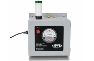
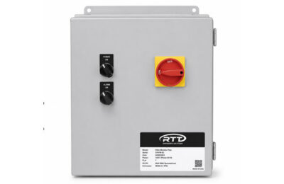
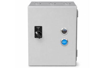
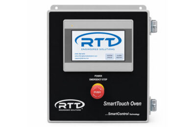
RTT offers pre-wired motor starters, UL-listed control panels, VFD controls, and optional touchscreens to simplify operation, fan speed adjustment, and booth balancing. All panels feature a single-point connection for quick and easy installation. In addition, we offer monitoring systems that allow you to optimize the performance of your finishing system.
Filter Monitoring System
- Controls
UL Listed Standard
- Control Panels
Magnetic Motor Starter
- Control Panels
SmartTouch Touchscreen
- Control Panels
Variable Frequency Drive
- Control Panels

Paint Booth Filters
RTT offers a wide range of replacement paint booth filters — built from virgin paper materials and stocked for fast lead times. Whatever your application or filtration efficiency requirement, we have a solution ready to ship.
3200 Spra-Gard High Efficiency
- 3XXX-Series RP Paint Arrestors
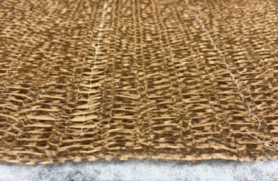
3300 Spra-Gard High Efficiency
- 3XXX-Series RP Paint Arrestors
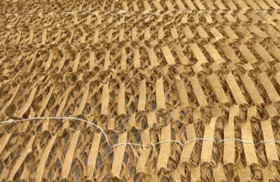
3400 Spra-Gard High Capacity High Efficiency
- 3XXX-Series RP Paint Arrestors
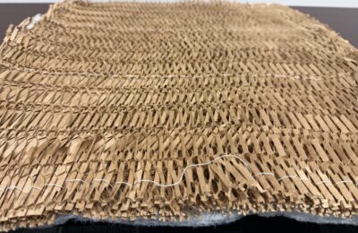
3600 Spra-Gard High Capacity High Efficiency
- 3XXX-Series RP Paint Arrestors
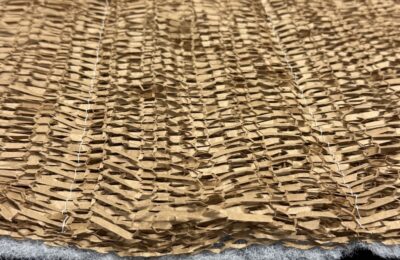
3700 Spra-Gard High Capacity High Efficiency
- 3XXX-Series RP Paint Arrestors
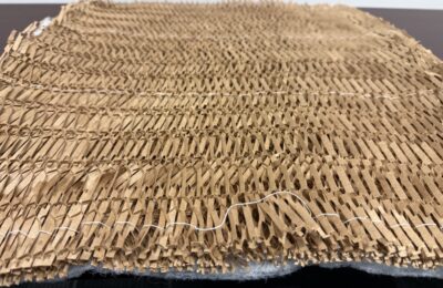
W-5000 High Efficiency
- W-Series RP Paint Arrestors
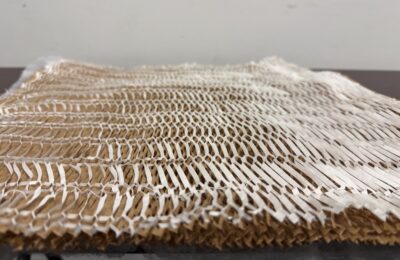
W-5100 Ultra Efficiency
- W-Series RP Paint Arrestors
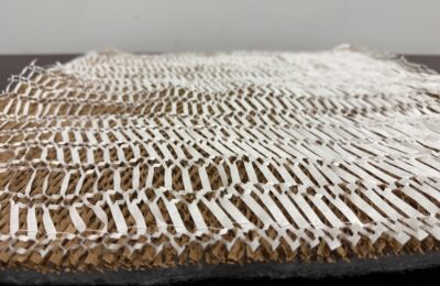
W-5200 High Capacity Ultra Efficiency
- W-Series RP Paint Arrestors
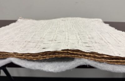
Services
RTT provides end-to-end services tailored to every phase of your project, so you never have to look further than one trusted partner.
Custom Engineered Solutions
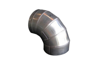
Ductwork
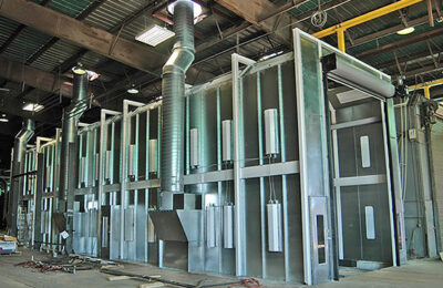
Installations
Maintenance
Product Training

Help and Support
Access the resources, documentation, and technical support information you need to keep your RTT equipment operating safely, efficiently, and at peak performance.
Product Literature
Extending the Life of Your Spray Booth
Frequently Asked Questions
When Should I Change the Filters on My Spray Booth?
When it comes to determining when to change your spray booth filters, first we must differentiate between intake filters and exhaust filters. Intake filters are located where the outside or shop air is introduced to the spray booth working environment. These filters work to ensure that the air introduced into the spray booth is free from debris, which can cause defects in your coatings. Exhaust filters are in separate locations, depending on the design and construction of your spray booth. The primary function of these filters is to capture overspray from the booth working environment and prevent harmful and hazardous particulates from being exhausted into the atmosphere by the booth exhaust fans. The function of both filter types is paramount to the spray booth functioning properly and ensuring the best possible coating finish. Spray booths are designed to meet National Standards, such as OSHA and the NFPA.
When filter maintenance is neglected, the performance of the spray booth will fall below the standards’ requirements. When the spray booth performs below the designed param¬eters, proper airflow will not be present and the likelihood of overspray or dust to accumulate on the coated part increases exponentially. Because there are many different filter constructions available, it is difficult to mandate a certain time interval for filter change outs. There are many other factors that play a part in the life span of the filters, including cleanliness of the surrounding environment, type of coating being sprayed, application styles and equipment used, spray booth air speed, spray booth design and construction and design of the filters can all affect the life of the filter. However, there are some key indicators that your filters are coming to the end of their effective life span:
Intake Filters:
• When an increase in debris or dust is noticed in the booth or in the coatings.
• If you have a manometer or Magnehelic gauge to measure pressure, drop through the filter, change at the suggested loading of the manufacturer.
• Filters have been installed for six months.
Exhaust Filters:
• When overspray is noticed to be lingering in the booth more than usual.
• The spray booth fan is operating at 100% capacity.
• If you have a manometer or Magnehelic gauge to measure pressure, drop through the filter, change at the suggested loading of the manufacturer.
• Applying a coating that is capable of spontaneous combustion or other harmful compounds.
• Filters have been installed for one month.
It is best practice to establish a filter maintenance program with the help of RTT Finishing Solutions. Improper filter maintenance can affect more than just the finished coating. It can also affect the health and safety of your employees as well as the profitability of your business.
Where Should the Temperature Sensor Be Located on My Spray Booth?
RTT recommends that the temperature probe be in the discharge ductwork of the Air Make-up Unit (AMU). The probe is to be located as far from the discharge location of the AMU as possible before entering the paint booth intake plenum. This configuration helps to avoid sharp spikes in temperature and will even out the ramp and soak time of the burner. Eliminating the possibility of an over-temperature situation inside the AMU. In rare instances, the temperature probe may be in the intake plenum of the spray booth. Please consult with RTT Technical Support before locating the temperature probe anywhere other than the AMU discharge ductwork.
Why Are My Spray Booth Doors Being Blown Open?
This is typically caused by excessive incoming gas pressure affecting system balance. When gas pressure exceeds regulator ratings:
• Airflow and burner output become unstable
• The system may create positive pressure inside the booth
• Doors can blow open due to improper pressure differential
Check the valve train regulator, system gas pressure, and follow the manufacturer’s recommended pressure ranges.
My Spray Booth and Oven Controls Require a Password to Change Settings - What Is It?
Operator passcode is 2050
Oven – All passcodes in the Oven Operation & Maintenance manual. Maintenance passcode is 1111
My Exhaust Fan Is Not Running Even Though My Booth Has Power — What Could Be Causing It?
There could be several issues that could cause your exhaust fan not to operate. If you have confirmed you have power, do you have a fault on your Variable Frequency Drive (VFD)? Check to see if there is a fault code displayed on the VFD. Depending on the make and model of your VFD these codes can differ.
Related Products
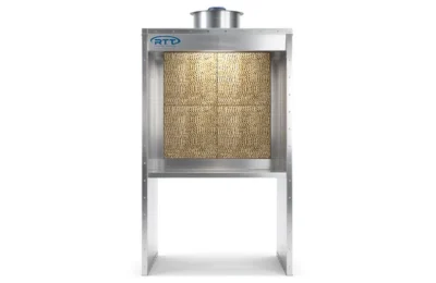
Open Front Bench
- Industrial Paint Booths
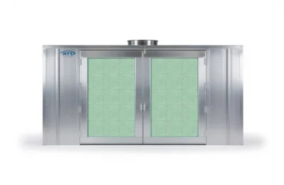
Enclosed
- Industrial Paint Booths
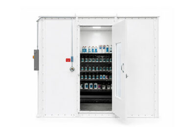
Industrial Paint Mixing Room
- Preparation Equipment
FilterLoc Paint Booth Seal
- Accessories
Tubeaxial Fan
- Accessories